By Bill Turkington
Part One: The equipment in my setup
Foam wings became popular in the 1960's when modelers quickly figured out that they made the job of building a tapered wing a lot easier. The first type of foam wings were constructed of 1# EPS foam that was covered with 1/16" Balsa sheeting applied with Epoxy glue or contact adhesive. This type of construction was popular for .40 and .60 sized glow engine R/C aircraft which ruled the sky of most R/C fields at the time. The finish was typically Monokote or one of many heat shrink covering materials. Not surprisingly, this type of foam wing construction works well for many types of aircraft and is still very popular today.
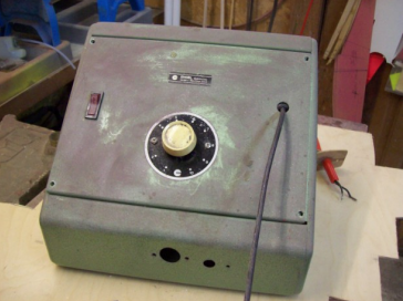
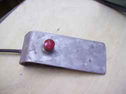
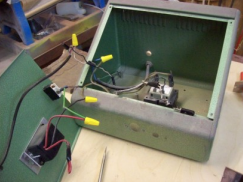
My setup: To heat the wire in the cutting bows, I use a 24volt transformer wired to a rheostat/dimmer switch. As part of the circuit there is an on/off switch and a 2 pole plug which connects a foot switch to control the heat to the bow. "Look Ma no hands".
The rheostat is necessary to control the amount of current going to the bow, the shorter the bow the less current required.

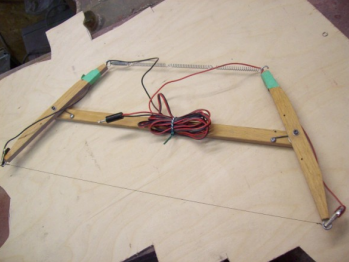
The cutting bows are made from hardwood (I have three bows of various lengths to handle any size job), and the wire is nichrome available from hobby shops, under the Sig name. Crocodile clips are used to connect the heat source to the wire. Springs or rubber bands used to tension the wire.
Part Two: The foam wings
1) Wing of equal chord. Cut two rib templates exactly the same from 1/16" ply, run a bead of thin CA glue along the edge of both to harden so the hot wire won't dig into the wood. Rub with fine grade sandpaper to make the edges smooth. When marking out the rib templates allow an extension on the Leading and Trailing edges, for a lead in and a lead out for the cutting wire. Cut two white foam blanks from the wing plan each half the span less the tips, use foam 1/2" more than the widest part of the rib templates, mark a datum line on each template, which is the wing incidence line, and also on both ends of the foam blanks. Make sure these are marked accurately so as not to cut a twist into the wing. Drill several holes in the rib templates for pinning the templates to the foam. I use 1" panel nails and drill 5/64" holes. Pin the templates to the ends of the foam blanks, making sure they are lined up. Place a weight in the middle of the foam to prevent it moving, then set the hot wire on the lead in on each template, switch on the heat and move the wire with a steady pressure along the templates, try to keep the wire parallel to the LE/TE of the template, and try to keep the wire moving, because if the hot wire stops it will burn a groove in the foam. Do the same to the bottom of the wing, and what do you know, you have half a foam wing!! Cut the other half, add the balsa leading and trailing edges, and tips, I have found that wing spars are unnecessary, then prop the tips up for the dihedral, and sand the roots to the correct angle. I have covered foam wings with 1/16' balsa, 1/64" ply, wood veneer, and even cardboard, whatever turns you on.
2) Tapered wings. Cut two templates for the root and tip ribs, and prepare them as described above. Mark each rib template with ten equal spaces and mark the lines from 1-10, starting at the trailing edge of each rib. Cut two foam blanks as per the plan, don't forget you will need a left and right, in this case. Mark the incidence lines as before, but usually the tapered wings will have built in wash out. If this is the case, mark the washout angle on the tip of the foam blanks and set the tip rib template to this angle. Make sure both wings halves are identical. When cutting tapered wings it is good to have help, so you have to put your wife through a vigorous training schedule before commencing to cut. So with your helper at the root and you at the tip, turn on the heat and move the wire along from #1 to #10. Both should be at the same number all the way, both should call the number as it is reached. If you are at 10 and she is at 3, we have to go back and continue with even more vigorous training, which may involve divorce lawyers..!
Part Three: Foam Floats - My Way
Formula for size and shape.
- Length of the float = 75 to 80% of fuselage length, measured from rear of spinner to TE of elevators
- Depth of the float = 10% of length plus step.
- The step 1/2" minimum depth.
- Width 2" minimum at top. According to weight of model.
- Step to be at 50% of length
- Rear slope to be 5 degrees from step.
- Front slope to be 5-7 degrees from step with a gentle curve to tip.
Make a side view pattern out of bristol board or similar material. Hot wire guide strips are required; two straight edge strips 1/2 X1/8 X36 and two curved patterns from 1/16 ply to match the front, from the step forward. Note: the bottom fronts of the floats are” V’d” and the rear bottoms are flat.
Cut two foam blanks, length, width and height as above, tape them together side by side, and using the bristol board template, mark both sides of the block.
Make a saw cut across both blanks at step location. Cut down just past the rear sloped line. Insert a piece of 1/16 ply into the slot the same width as both blanks, and past the line of the rear slope, this will act as a stop and prevent the hot wire cutting past the step.

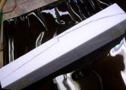
Pin the straight strips along the rear sloping lines on both sides. Using the guides, hot wire the foam until it stops at the plywood insert. Separate the two blanks, and this is what you should have.
To taper the sides, tape the rear piece in place again temporarily, and mark the top of both to the desired dimension, pin one straight edge along one top line and the other along the bottom flush with the edge. Hot wire both sides of both blanks in this manner, remove and discard lower rear pieces, and you should have two pieces like this.
Mark the front bottom curve on both sides of each float and pin the curved templates to each side as shown. Outside line first. Hotwire, then set up for the Vee bottom. Mark a centre line on the bottom front and mark the Vee on the step and at the tip. Hot wire or sand the Vee. To hot wire, pin a curved template to the inner curve, then lay a straight edge on this at the step to the centre line and pin the other curved template to guide the wire along the centre line. Repeat for float two!!
Before covering I glue a piece of 1/16 ply to the step to reinforce and prevent crushing the foam at this point, I also glue a length of 3/32 square strip to the centre line of the bottom front Vee. Note: Use epoxy, CA will make your foam floats disappear. I then cover the floats in 1/16 balsa with the grain running length ways on the sides and top, and cross grain on the rear bottom. The front bottom is covered with 3/32 balsa, two pieces from the centre out, cross grain.
Use water based contact cement. Finish the floats with balsa tip blocks and plywood stern posts, 1/8 or 1/4 ply depending on float length.
I fibreglass the front bottom of my floats, as this is where all the hard knocks occur, but this is optional. Have fun!! Bill